| Welcome to Sprocket School! This project is maintained by volunteer editors. Learn more about how this works. |
Kelmar RTV-8900: Difference between revisions
JesseCrooks (talk | contribs) m (Removed broken link) |
JesseCrooks (talk | contribs) m (→Friction Clutch: Typo) |
||
| Line 77: | Line 77: | ||
Check periodically for dirt and wear. Remove the knurled nut, spring, and pressure plate. The felt pad is retained by a spring pin, which can be difficult to remove if there is significant dirt built-up. If the pin is relatively loose, a 5/32 Allen wrench can be used to drive it out. If the pin is difficult to remove, it can be driven through using a pin punch. Remove the pin to free the felt pad. Clean the pad as necessary and replace it when worn. The pad can be cleaned with a spray degreaser like 409 or a degreasing dish detergent to keep it clean. Apply the degreaser, rub it in with a cloth to remove any oil, wipe it off and clean it with a paper towel, and rub it dry. Let the pad fully air dry before reinstalling. This should be done once a year if film is run infrequently. Always stock spare felt pads so that a worn pad can be replaced immediately. | Check periodically for dirt and wear. Remove the knurled nut, spring, and pressure plate. The felt pad is retained by a spring pin, which can be difficult to remove if there is significant dirt built-up. If the pin is relatively loose, a 5/32 Allen wrench can be used to drive it out. If the pin is difficult to remove, it can be driven through using a pin punch. Remove the pin to free the felt pad. Clean the pad as necessary and replace it when worn. The pad can be cleaned with a spray degreaser like 409 or a degreasing dish detergent to keep it clean. Apply the degreaser, rub it in with a cloth to remove any oil, wipe it off and clean it with a paper towel, and rub it dry. Let the pad fully air dry before reinstalling. This should be done once a year if film is run infrequently. Always stock spare felt pads so that a worn pad can be replaced immediately. | ||
Clean the spring pin, pressure plate, and clutch plate, and check for wear. If the pressure plate is worn, it can be flipped to use the other side. If the clutch plate worn or pitted, super fine steel wool (#0000) can be used to smooth down the plate. | Clean the spring pin, pressure plate, and clutch plate, and check for wear. If the pressure plate is worn, it can be flipped to use the other side. If the clutch plate is worn or pitted, super fine steel wool (#0000) can be used to smooth down the plate. | ||
Do NOT apply oil to the felt pad. This will attract dirt, and will cause the friction level to drift much faster than would occur due to natural wear on the felt pad. This throws the friction clutch out of calibration and requires re-oiling. An overly oiled pad will also spray oil when it rotates, making a mess and possibly leading to [[print contaminant|print contamination]]. | Do NOT apply oil to the felt pad. This will attract dirt, and will cause the friction level to drift much faster than would occur due to natural wear on the felt pad. This throws the friction clutch out of calibration and requires re-oiling. An overly oiled pad will also spray oil when it rotates, making a mess and possibly leading to [[print contaminant|print contamination]]. | ||
Latest revision as of 13:53, 17 January 2022
The Kelmar RTV-8900 is a versatile rewind table that can accommodate 16mm, 35mm, and 70mm film, and provides excellent control of motor speed and holdback tension. It features a variable speed bidirectional motor, an adjustable friction clutch for regulating feed tension, interchangeable spindles to accommodate various film gauges and reel sizes, a built-in light box for film inspection, and an automatic rewind system. The RTV-8900 comes in a full-size 24” deep version or a slim 14” version. A model with two power heads is also available.
The control unit and rewinds can also be attached to other tables (ex., to replace hand-crank rewinds on vintage rewind benches).
Use

- Never leave the table unattended when rewinding film.
- Limit motor power to 20% during inspection and 30% for rewind when handling archival materials. Never exceed 40%.
- Your hand should never leave the throttle control when film is being rewound, especially during inspection.
- Make sure this is no slack in the film before starting the motor.
- Always adjust motor speed gradually to prevent damage.
- If the STOP button is used, always dial the motor speed back to zero to prevent a sudden start.
- Make sure that the spindles are fully seated. If not, they can shift towards the operator, resulting in a misaligned film path and improper rotation.
- When winding backwards off the takeup reel, make sure to set the takeup direction to neutral and rotate the reel backwards with your hand (do NOT pull on the film to rewind it, which will cause cinch scratching). Reversing the motor direction to feed the film back for long distances is not advisable because it gives you less control, and it risk spilling film onto the floor.
- The guide roller on the automatic rewind arm can sometimes help achieve a smoother wind for film that is spooling unevenly. However, for archival projection it is often better to remove the roller so that it is not an obstacle in the film path. If you do use it, clean it with alcohol before each use. If a white roller is available, it will make dirt more visible (white Kelmar guide rollers designed for use with platter systems are compatible with the auto-shutoff).
- Always remove spindles when not in use. If someone walks into them, they are easily bent.
Tip: In low humidity or when winding between two plastic reels, static can build up during rewind. While holding the film with your left hand to inspect it, you can ground yourself by placing the finger of your right hand on the edge of the throttle control knob where it meets the metal case. This will dissipate any static build-up and prevent you from getting shocked.
Parts & Accessories

- Interchangeable spindles
- 5/16” with key (standard spindle for reels up to 3,000’)
- 5/16” with extended key for plastic shipping reels (reduces wear on plastic keyway; especially beneficial for reels with detachable flanges)
- 5/16” with drive pin (also called a “reel dog”) for large reels
- 5/16” with finger hole drive for large reels
- 1/2" with drive pin for large 35mm reels (shorter than 70mm shaft)
- 1/2" with finger drive for modular platter reels
- 9mm with drive pin for European reels
- 70mm shaft with drive pin (1/2" shaft, longer than the one used for 35mm)
- 16mm shaft (square shaft base)
- Handle for manual rewind
- Mounting bracket for a Neumade Film Measuring Machine
- Screw mount on the front of the table accommodates a bracket to hold a Neumade frame counter. This allows the frame counter to align with the film path.
- Replacement belt
- Belt size: 3L260 V belt
- Available at most small engine repair shops
Calibration
Feed Tension
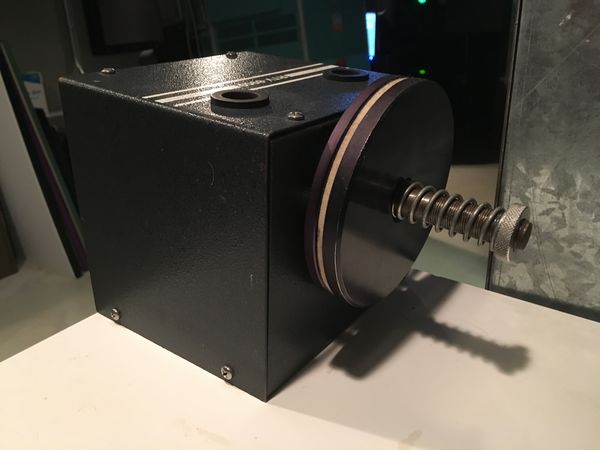
The feed tension is regulated by a friction clutch on the drag head. Friction is maintained by a felt pad that is pressed between the clutch plate and a pressure plate. Pressure is regulated by a spring on the back of the clutch, which is held in place by a knurled nut. Adjusting this nut increases or decreases holdback tension.
Film Path Alignment
The lateral alignment of the film path is determined by the placement of the power and drag heads, which are bolted to the table top. Loosen the bolts to adjust the angle of the heads and their distance from the edge of the table top. This lateral adjustment will resolve most alignment issues.
It is also possible to adjust the pitch of the film path by adjusting the height of the spindle receiver in relation to the rear bearing. In most cases, they should be perfectly flush. To make this adjustment, remove the cover of the head and loosen the lock nuts securing the flanges covering the spindle receiver. Adjust the height of the spindle receiver and retighten. This adjustment can also be made at the other end of the shaft by loosening the nuts that secure the flanges around the rear bearing.
Spindle Detente
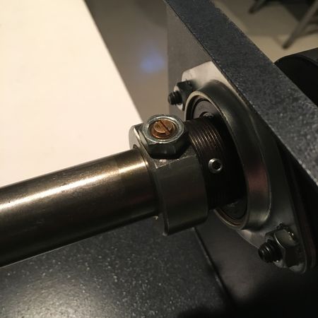
When the spindle is inserted into the receiver, a detent pin locks it in position. If the spindle is too difficult to insert or remove from the spindle receiver, or if it slips out too easily, the pressure with which the detent holds the spindle in place can be adjusted. Remove the cover of the head and locate the detente, which is a screw head held in place by a lock nut in a collar on the spindle receiver. Loosen the lock nut to free the detente, adjust it to the desired position, and retighten the lock nut.
To adjust the detent on the main drive shaft, it may be necessary to move the pulley away from the detent collar in order to have enough room to rotate the lock nut. To reposition the pulley, loosen the set screw located on the shoulder of the non-operator side. If you adjust the pulley, check the belt alignment after you’ve returned it to its original position.
Belt Alignment
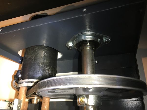
To align the belt, adjust the position of the pulleys. The pulley on the drive shaft is secured by a set screw in the middle of the belt groove, and the pulley on the main shaft is secured by a set screw on the shoulder that extends from the pulley on the non-operator side.
First make sure the pulley on the main shaft is backed up against the collar that holds the spindle detent, which is always in a fixed position on the shaft. Then adjust the drive pulley to align with the pulley on the main shaft.
Run the motor at a low speed and check the alignment. If the alignment seems adequate, gradually increase the motor speed, visually assessing the alignment, checking for contact between the belt and motor standoffs, and observing for any noises or vibrations that might indicate that something is wrong.
To achieve adequate clearance between the belt and the motor standoffs, it may be necessary to turn the drive head on its side, with the motor facing down in order to use gravity to assist the alignment. However, it is also possible to over-tighten the belt in this manner. If excessive vibration is detected after alignment, the belt may be too tight and the motor may need to be moved closer to the main shaft. If it is impossible to achieve adequate clearance between the belt and the motor standoffs (in addition to being gauged by eye, a lack of clearance will be evidenced by belt shaves being worn off due to contact with the standoffs), the standoffs maybe be filed down to prevent contact with the belt.
-
Belt running from drive pulley (left) to main pulley.
-
Collar holding the spindle detent pin in the drag head. Loosen the lock nut to adjust the pin.
Maintenance
Cleaning
Clean all surfaces with 99% alcohol before and after use. Periodically remove the cover of the power and drag head and clean inside as necessary.
Spindles
To prevent rust, the spindles and spindle receivers can be lightly lubricated with a couple drops of oil. Wipe off any excess oil and clean any other surfaces that may have gotten oily.
Friction Clutch
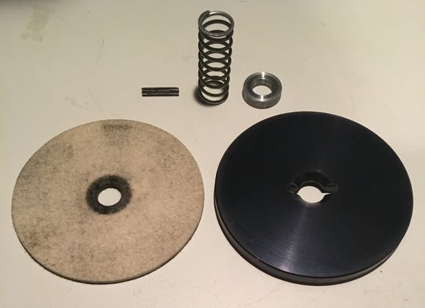
Check periodically for dirt and wear. Remove the knurled nut, spring, and pressure plate. The felt pad is retained by a spring pin, which can be difficult to remove if there is significant dirt built-up. If the pin is relatively loose, a 5/32 Allen wrench can be used to drive it out. If the pin is difficult to remove, it can be driven through using a pin punch. Remove the pin to free the felt pad. Clean the pad as necessary and replace it when worn. The pad can be cleaned with a spray degreaser like 409 or a degreasing dish detergent to keep it clean. Apply the degreaser, rub it in with a cloth to remove any oil, wipe it off and clean it with a paper towel, and rub it dry. Let the pad fully air dry before reinstalling. This should be done once a year if film is run infrequently. Always stock spare felt pads so that a worn pad can be replaced immediately.
Clean the spring pin, pressure plate, and clutch plate, and check for wear. If the pressure plate is worn, it can be flipped to use the other side. If the clutch plate is worn or pitted, super fine steel wool (#0000) can be used to smooth down the plate.
Do NOT apply oil to the felt pad. This will attract dirt, and will cause the friction level to drift much faster than would occur due to natural wear on the felt pad. This throws the friction clutch out of calibration and requires re-oiling. An overly oiled pad will also spray oil when it rotates, making a mess and possibly leading to print contamination.
-
Assembled friction clutch.
-
Spring pin, spring, knurled nut, felt pad, and pressure plate disassembled for cleaning.
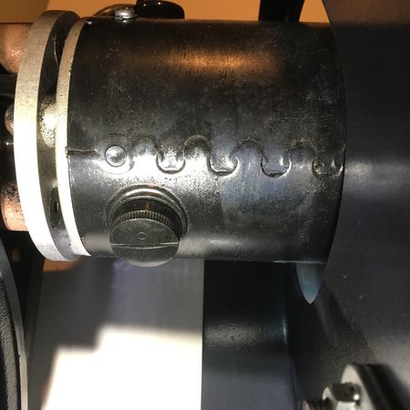
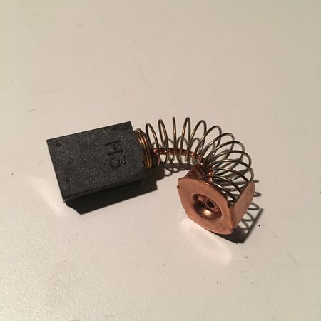
Motor Brushes
The brushes in the drive motor will wear down over time, and Kelmar recommends that they be replaced when their overall length is 5/16” or less. To inspect the brushes, unscrew the plastic cap on the side of the motor and remove the brush. There is one brush on each side of the motor.
-
Motor brush cap.
-
Motor brush.
Belt Replacement
Belt wear can cause slippage, lost motion in the takeup, and a laboring takeup (especially for large reels or 70mm). If you feel the tension slipping or hear thumping or other noises that may indicate a problem, remove the cover to check the belt for wear. Upon inspection, a belt may exhibit cracking, or the text printed on the belt may show stretching and wear.
To replace the belt, the motor and the rear bearing of the main shaft have to be disconnected from the cover.
To free the motor, remove the cap screws that secure the motor standoffs to the front cover. If the gray wire running to the auto-shutoff microswitch is zip-tied to the motor standoff, you may have to cut the tie. Alternatively, you can disconnect the microswitch from the front cover and remove it with the motor.
With the motor free, turn it towards the main shaft to take tension off the belt. Slip the belt off the drive pulley and then off the main pulley. With the belt loose, unscrew the flanges on the rear bearing of the main shaft and detach the bearing from the rear cover. Slip the belt around the main shaft and remove it.
Note: The old belt can simply be cut to remove it, but you will have to loosen the same parts to install the replacement. Doing it this way also ensures you have the tools required to install the new belt before you render your rewind table useless by destroying the old belt.
To install the new belt, pass it through the opening around the rear bearing of the main shaft and slip it around the main shaft, without yet placing it on the main shaft pulley. Slip it around the drive pulley and reinstall the cap screws that secure the motor standoffs, but leave them loose. Slide the motor towards the main shaft to provide enough slack to slip the belt onto the main shaft pulley. Pull the motor away from the main shaft, making sure that the belt is not making contact with the motor standoffs. When the motor is in a good position, tighten the cap screws to secure it.
Tip: If you’re having difficulty getting the belt to clear the motor standoffs, standing the power head on its left side will allow you to use gravity to your advantage.
After the belt has been reinstalled, run the motor at a low speed and check the alignment. If the alignment seems adequate, gradually increase the motor speed, visually assessing the alignment, checking for contact between the belt and motor standoffs, and observing for any noises or vibrations that might indicate that something is wrong. Replace the cover and continue to test by rewinding a reel of scrap film. Also check the pitch of the film path since the position of the main shaft may have changed when it was reattached.
Once you have determined that the new belt is working properly, it’s a good idea to open up the head after it’s seen a few hours of regular use. Inspect the belt to see if it’s still clearing the motor standoffs, and look for belt shavings that may have rubbed off from contact with the standoffs. If you have been experiencing issues with the belt hitting the standoffs, you can replace the belt with one of a different color so that the belt shavings will be an obvious indicator if the problem persists.

Common Issues
- Contact between belt and motor standoffs. The surface of the standoffs can be ground down where the belt is making contact to give the belt adequate clearance.
- The table surface around the bolts is often damaged due to over-tightening or the use of excess force during rewind. The mica laminate is easily cracked, and the particle board underneath is very weak. Replace washers with a larger size to cover any damage and distribute the pressure over a greater surface area.
- Kelmar spindles are somewhat weaker than other models. If the spindles get bent or become orbital (the tip of the spindle will wobble rather than spinning evenly on its axis) replace them.
- The throttle knob is connected to a carbon wiping brush that controls a variable transformer to regulate motor power. This brush can wear down, causing the motor to cut out intermittently at lower speeds. It will still operate normally at higher speeds, because the higher current can arc despite the worn brush. If the motor is cutting out at low speeds, contact a service technician for repair.
Moving a Kelmar table
Kelmar tables are made of relatively weak materials, and are prone to damage if moved when fully assembled. Specifically, the particle board table top is easily stressed and the sheet metal braces are easily bent. When moving a Kelmar table for more than a short distance, it should be disassembled. The table should always be moved by two people.
Disassembly
- Disconnect the wiring from the drive head to the control unit and unplug the power cable.
- Remove the power head and drag head. Loose wires can be wrapped and tucked into the drive head for transport.
- Remove the control unit.
- Remove the plexiglass light box cover.
- Place the table upside-down on the floor, with cardboard or another material in place to protect the surface of the table top.
- Remove the crossbar connecting the legs.
- Remove the legs.
Tip: The automatic rewind arm can be removed from the power head for transport. The screw that connects the arm to the auto-shutoff cam also prevents the cam from slipping back into the head. After removing the arm, replace it with a washer to secure the cam.
Reassembly
- Assemble in reverse order.
- When mounting the heads, It is advisable to replace the washers with a larger size, especially if damage is already present around the bolts.
- Once the table is in position, level the feet.
- Take care to realign the heads after the table has been reassembled.
External links
- Kelmar RTV-8900 Manual
- Kelmar website - See the Archival Products Catalog for film equipment.
